Fire scares buyers and ruins brands. I saw one shipment recalled for heat damage. The root causes were simple, hidden, and preventable. I now use a strict checklist.
Most charger fires1 trace to poor soldering2, cheap parts3, weak insulation distance4, bad thermal design5, or blocked protection circuits6. Good design, certified parts, and real factory tests prevent almost all incidents.
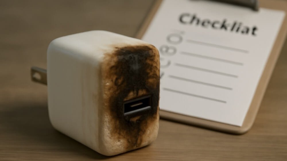
I will keep this clear and direct. I will show why chargers fail, how to build them safe, and how to judge a supplier. I will share my own audit steps that I use in OEM orders.
What are the causes that lead to a charger explosion?
Bad joints spark. Dross bridges tracks. Weak parts pop. Poor creepage arcs under stress. Hot layouts cook caps. I have seen each one in factory audits and after-sales returns.
The main causes are cold solder joints7, solder dross shorts8, low-quality components9, unsafe creepage and clearance10, and thermal runaway11 from poor design. Surge, ESD, or lightning then push them over the edge.

The failure paths I watch
I split the risks into five clear buckets. Each bucket maps to a factory control. When one control is missing, risk jumps. When two are missing, fire risk becomes real.
1) Assembly defects
- Cold solder joints crack under heat and vibration. Resistance rises. Heat builds. Nearby plastic softens. Short follows.
- Solder dross or splash bridges high-voltage (HV) and low-voltage (LV) pads. This makes instant shorts when humidity is high.
2) Component quality
- Fake or downgraded MOVs, fuses, and Y capacitors fail to open correctly. Surges go straight to the primary side.
- Cheap electrolytic capacitors dry out fast. Ripple rises. Heat climbs. The primary switch overstresses.
3) Insulation distances
- Creepage and clearance below IEC 62368-1 spec allow arcs. Dust and moisture make it worse. I saw carbon tracks form across slots in one bad PCB.
4) Thermal design
- Transformers placed tight to hot switches raise core temp. Plastic cages deform. Coil varnish browns. The unit then smells, hisses, and can fail hard.
- No airflow path or tiny shells trap heat. PPS modes can push sustained high current and reveal weak spots.
5) Protection logic
- Missing or wrong OCP/OVP/OTP/OPP settings let faults run wild. A simple short should fold back output. If not, copper traces act like fuses.
| Cause | Typical Trigger | Early Symptom | Final Failure |
|---|---|---|---|
| Cold solder | Vibration/heat | Intermittent charge | Arc/short |
| Solder dross | Humidity/transport | Random reset | Short/fire |
| Bad parts | Surge/load spike | Buzz/swell | Burst, smoke |
| Low creepage | Dust/moisture | Charring marks | Arc/flash |
| Hot layout | Long high load | Hot shell >70°C | Melt/ignite |
What methods can manufacturers use to prevent the products from exploding during use?
Prevention is process. I do not accept slogans. I ask for proof in each step. Good factories can show it in minutes. Weak ones give stories.
Use strict incoming inspection12, safe PCB layout with correct creepage, controlled soldering, full PCBA tests, 100% functional tests, aging at load, and high-voltage withstand tests13 with records and traceability.
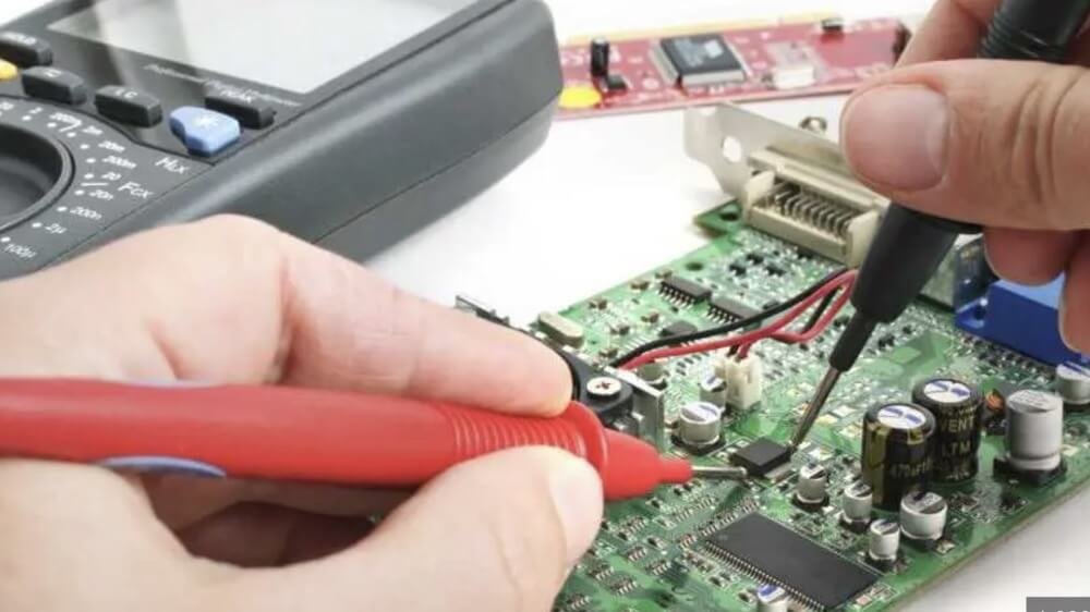
The control chain that works
I map controls from parts to pack-out. Each step cuts one failure path. When all steps run, field returns drop to near zero. I have seen this in monthly RMA charts.
Incoming material inspection (IQC)
- Verify fuses, MOVs, Y-caps, primary switches, and capacitors by lot. Check datasheets and test reports. Spot-check with LCR and surge tests.
- Reject lots without traceable COC, RoHS, and safety marks.
PCB and layout design
- Meet IEC 62368-1 creepage/clearance. Use slots under optocouplers. Keep HV and LV separated. Add shielding copper with proper spacing.
- Place thermal parts apart. Add NTC/OTP sensing on the hot spot.
PCBA process control
- Use controlled solder wave or reflow profiles. AOI after solder. Manual touch-up under magnifier to remove dross.
- Conformal coating for humid markets if needed, but never to hide bridges.
Electrical protection
- Set OCP, OVP, SCP, OTP, OPP in firmware/hardware. Validate with load steps and shorts. Check foldback behavior on all ports and splits.
Full tests
- ICT/FCT on PCBA for key rails and protocols. 100% function on finished goods. 100% Hi-Pot between primary and secondary.
- Aging: run 45–60 minutes at 70–80% load, ambient 35°C. Log failures.
| Step | Test/Control | Pass Criteria | Evidence |
|---|---|---|---|
| IQC | Parts ID + spot tests | Meets spec | Lot sheet + photos |
| Layout | DFM + safety review | Creepage OK | Signed drawing |
| Solder | AOI + visual | No voids/bridges | AOI reports |
| PCBA | ICT/FCT | All rails stable | Test logs |
| Hi-Pot | 3kVac 1s | No breakdown | Machine log |
| Aging | 45–60 min | 0 failures | Aging list |
| Final | Function + visual | Label/spec OK | QC sheet |
How can you assess the quality of the products produced by your supplier?
I do not trust words. I trust process data, real certificates, and random tests. I set this rule in every PO. It keeps my brand safe.
Audit the factory, verify real safety reports, review QC records per lot, and run third-party sampling tests14. Tie payment to pass results. Keep one sealed golden sample.

My buyer-side checklist
I learned these steps after one painful return season. Since then, claims dropped and lead times stayed stable. The key is to lock proof before shipment.
1) Certification and reports
- Request CB to IEC 62368-1, CE/UKCA DoC, FCC, and energy reports. Verify report numbers on the lab website. Match photos and model IDs to samples.
- Check UK plug compliance: BS1363 fused plug, sleeved pins, correct fuse rating.
2) Process and capacity
- Ask for ISO 900115/14001, BSCI. Walk the line by video or in person. Look for AOI, Hi-Pot stations, and aging racks with real timers.
- Check monthly output and buffer stock of key ICs and capacitors.
3) Lot-level QC
- Ask for incoming IQC sheets, aging logs, and Hi-Pot logs for your lot. Check failure rate and rework notes. Randomly pick serials from the list and request photos.
4) Third-party sampling
- Send AQL inspection16 (e.g., II, AQL 0.65 major/1.5 minor). Add function, Hi-Pot, and short aging samples. For critical SKUs, send 5–10 units to a lab for fast verification.
| Area | What I Ask | Pass Signal |
|---|---|---|
| Certificates | CB/CE/UKCA/FCC + verify | Numbers valid, photos match |
| Process | AOI/Hi-Pot/aging proof | Live demo or logs |
| QC Data | Lot logs + failures | <0.5% during aging |
| Shipment | AQL + rework proof | CAR closed before ship |
What methods can manufacturers use to prevent the products from exploding during use?
Heat and surge are the main enemies. I design for both. I test for both. I do not skip either step, even for small 20W units.
Use surge protection17 (MOV/NTC/TVS), proper fusing, strong isolation, thermal sensors, and conservative power density. Validate with surge, ESD, load cycling, and high-temperature aging.
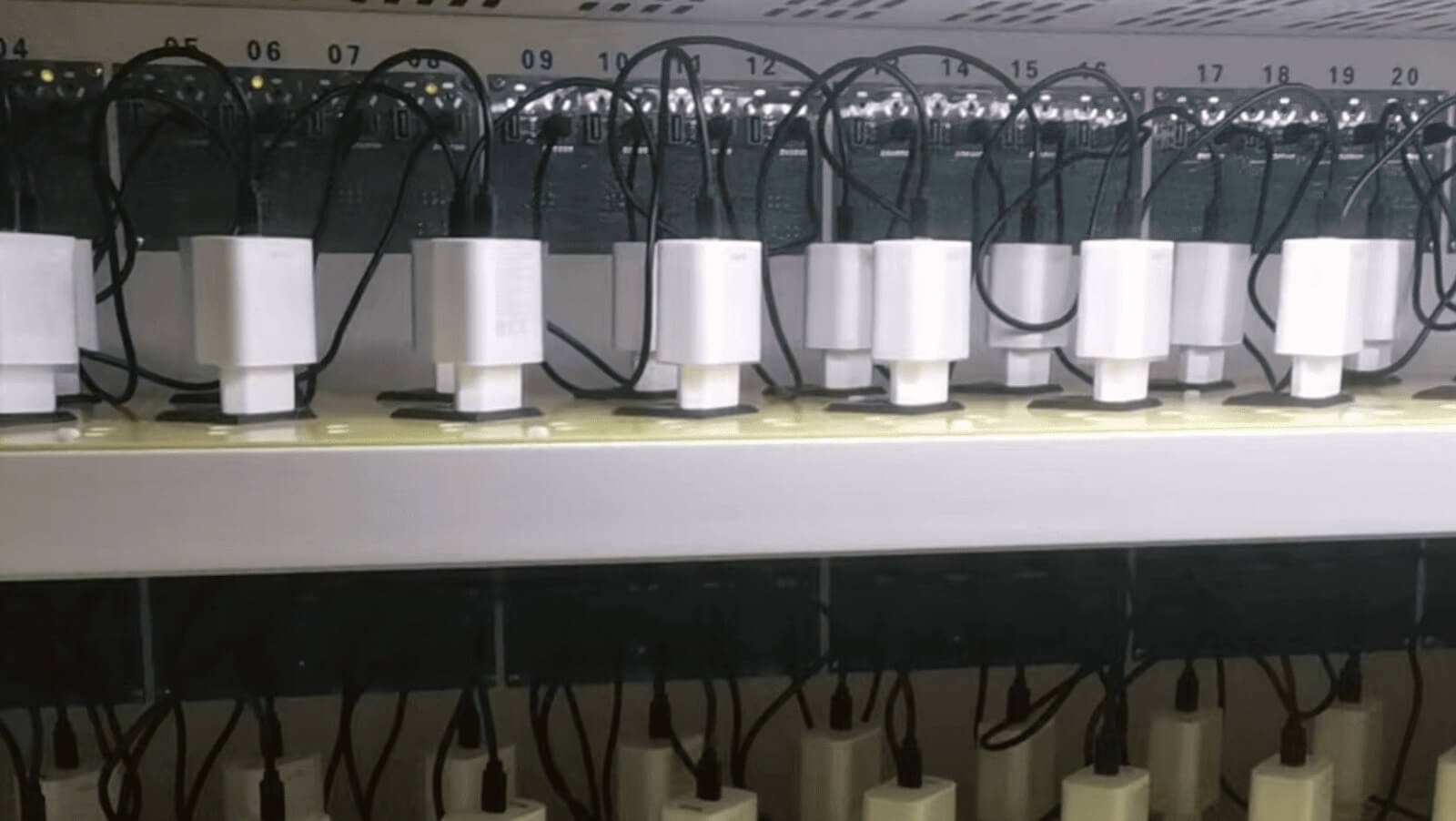
Design and validation playbook
I write these into the DVP&R before tooling. Good vendors welcome this. Weak ones try to skip steps. That alone tells me who to pick.
Protection stack
- Input fuse sized to open safely. MOV for surge. NTC to limit inrush. TVS on secondary for overvoltage spikes. Primary controller with reliable OCP/OTP/OVP.
- Y-capacitor with proper class and value. Transformer with triple-insulated wire or tape system that meets standard.
Thermal safety
- Spreaders or copper pours under hot ICs. Thermal pad to shell only if safe. Place sensors near switches. Trip at reasonable limits.
- Do not push tiny shells for marketing if airflow dies. Size still matters.
Validation tests
- Surge: 1–2 kV line surges, both polarities. ESD: ±8 kV air, ±4 kV contact. Run while charging a phone and a laptop.
- High-temp aging: 2 hours at 35–40°C, 70–80% load. Power cycle 1000 times from 0 to 100% load. Record and sign.
| Risk | Design Counter | Test to Prove |
|---|---|---|
| Surge | Fuse + MOV + controller | IEC surge test |
| Inrush | NTC/soft-start | Scope capture |
| Overheat | OTP + spacing | 2h soak at temp |
| Arc | Creepage/clearance | Hi-Pot + visual |
| Short | SCP/foldback | Hard short test |
How can you assess the quality of the products produced by your supplier?
I want proof I can read, not promises I can feel. Data and independent checks are my base. I keep it simple and strict.
Check certification, inspect the line, verify QC logs, and send random units to a lab. Align payments with pass reports. Keep traceable serials for every box.
My field method
I follow four moves every time. They protect my cash and my schedule. They also teach suppliers that I check everything.
Paper check
- Verify CB, CE, UKCA, FCC on lab portals. Match SKUs, photos, and voltage ranges. Reject “template” reports with stock photos.
Line check
- Confirm AOI, Hi-Pot, and aging are real with current logs. Ask them to print your lot labels in front of you or on video. Small ask, big truth.
Data check
- Ask for last three months of RMA and failure Pareto. If “no data,” I walk away. Good factories measure and share.
Third-party check
- Use AQL with function and safety spot checks. Keep golden samples sealed. Compare after arrival. If mismatch, hold payment.
| Check | Tool | Pass |
|---|---|---|
| Cert verify | Lab portals | Valid + matched |
| Process | Live demo | Stations working |
| QC data | Logs + Pareto | Stable, low fail |
| AQL | 3rd party | Within limits |
Conclusion
Fires come from bad joints, bad parts, weak spacing, and heat. Strong design and real tests stop them. Audit proof, verify reports, and sample-test every lot.
Understanding the causes of charger fires can help you prevent them and ensure safety. ↩
Learn how poor soldering can compromise electrical safety and performance. ↩
Discover why using low-quality components can lead to product failures and safety hazards. ↩
Explore the importance of proper insulation in preventing electrical failures. ↩
Understanding thermal design can help you create safer and more reliable products. ↩
Learn how protection circuits work and why they are crucial for safety. ↩
Understanding cold solder joints can help you improve manufacturing quality. ↩
Learn about solder dross shorts to enhance your soldering techniques. ↩
Discover the risks associated with using subpar components in your designs. ↩
Understanding creepage and clearance is vital for ensuring electrical safety. ↩
Learn about thermal runaway to design safer electronic devices. ↩
Explore how incoming inspections can prevent defects and improve quality. ↩
Understanding these tests can help ensure the safety and reliability of your products. ↩
Understanding third-party testing can enhance the credibility of your products. ↩
Learn how ISO 9001 certification can improve quality management in manufacturing. ↩
Discover how AQL inspection can help maintain high standards in production. ↩
Explore effective surge protection strategies to safeguard your devices. ↩


